A tale of a LED, or why Late Mate is taking me a while
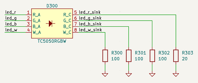
It took me two full working days to design this bit for Late Mate:

The end result is outrageously simple, why did it take so long? Read on and join me on the journey!
What do we want
As always, it all started with a "functional requirement", or a "user story": we want to have a LED directly opposite of the light sensor, showing the brightness seen by the sensor in real time. Done right, it should work like magic, as if this part of the device is transparent.
Additionally, we might want to indicate microcontroller states down the line, so ideally the LED should be full-colour. No better way to indicate problems than an angry flashing red LED!
Sounds simple enough.
But first we need to understand the problem space better.
White is not what it seems
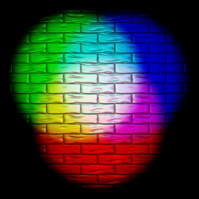
You might've seen an image like this:

Three primary additive colours (reg, green, and blue) look white when mixed together1.
Sadly, in reality the white colour we'd get from mixing three LEDs is crap and unstable. What we need instead is an RGBW LED: a special type of LED that has four LEDs inside it. W stands for White, an extra LED covered with phosphor that glows white.
Most multicolour LEDs are RGB, not RGBW.
Dim and difficult
Next difficulty: our eyes are too good. We perceive brightness logarithmically: if a scene gets twice as bright, we only see the change as a small brightness increment. This is amazing because we can see in the shadows on a summer day! It also means that monitors' brightness can vary a lot while looking similar to the eye.
On the sensor side we're tackling this wide range of brightnesses by going overkill with the sensor. Modelling suggests we should get about 16 bits of useful brightness data, which should be plenty to detect minute but repetitive brightness changes across a wide range of monitors.
On the other side (literally), the LED doesn't need to have the same precision, but it should still have a decent range of brightness it can display.
How do you dim a LED? Adjusting LED brightness directly is finicky, so instead you just turn it on and off real quick. If the LED is on for only half of every millisecond, it looks somewhat less bright to the eye2. The trick is to do this fast enough to avoid visible flicker. This is called PWM (Pulse-Width Modulation).
In our case it's also helped by the phosphor on the white LED: it has a very slight afterglow, helping to hide the flicker3.
To summarise, to make the magic work we want:
- RGBW LED
- fast enough PWM
- being able to dim down very low — this can exacerbate the flicker, because the LED is mostly off
- plenty distinct brightness values to make transitions smooth, especially when the LED is dim
All of the above needed to be researched or confirmed before proceeding, so that's half a day gone, even though I already knew most of it.
Taking stock
Our manufacturer of choice for prototype boards is JLCPCB, so the next stop is selecting the part. How hard can it be, right?

Oh.
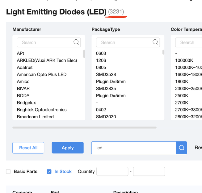
The parametric search is hit-and-miss, because many parts are labelled incorrectly or have slight variations in labelling ("460nm~464nm" and "460nm~465nm" are different). A neat trick I learned is to sort by stock, as more popular parts are usually better stocked. Searching for "RGBW" helped to limit the space a lot, too.
Still, it's dozens of datasheets to read through, some of which only come in Chinese.
First detour: "smart pixels"
Quickly I realised that some LEDs, such as the SKC6812 above, come with an integrated controller that does PWM.
Adafruit sells them as "NeoPixels", which is handy because they have translated datasheets. There are a number of those chips, some of which are in stock in JLCPCB.
Which means I have to read their datasheets, google, find reviews, compare, and consider.
Those integrated LEDs have a few pros:
- super easy to wire and control
- I can feed them straight from USB's +5V and control them by our MCU's 3.3V logic
But they also have downsides that convinced me to go with a traditional LED:
- fixed PWM frequency, best case around 1kHz, much lower for some LEDs
- best case 256 levels of brightness per colour
In contrast, RP2040's PWM peripheral can drive up to 65536 distinct PWM levels at frequencies up to high MHz, which gives us much more flexibility to experiment with duty cycles and get the brightness just right.
I still needed to find a "normal" RGBW LED to PWM. In the end this part seemed the most sensible, despite not having an English datasheet.
Second detour: LED drivers
At this point I asked myself if I should use a dedicated LED driver instead.
After a few hours I found out that stuff that JLCPCB has in stock doesn't make sense for us.
Third detour: transistors
Next stop: how to feed the LEDs? Instead of checking, I just presumed that GPIO pins won't be able to supply enough current to the LED, so I need a transistor circuit to amplify GPIO current.
For a long time I avoided educating myself on different transistor types (MOSFETs! BJTs! Darlingtons!), but I couldn't do so any longer. Time to read Wikipedia, The Art of Electronics, and random StackExchange replies!
It's only the next day, after selecting an appropriate MOSFET and drafting everything in KiCad, that it occurred to me to actually check RP2040's datasheet.
Simplicity is king
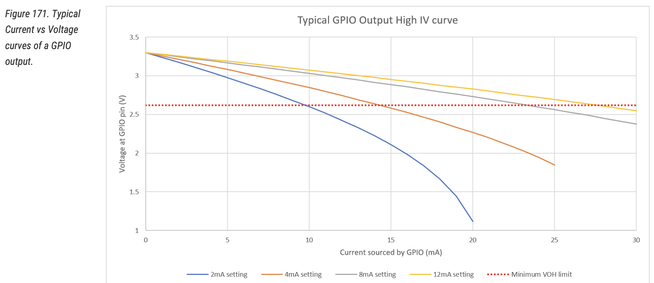
Lo and behold:

RP2040 can drive up to 15mA with a reasonable voltage drop of just 0.3V! Total GPIO power must stay under 50mA! What a delight! According to the LED's datasheet, with 10mA of current per LED I will still get more than 50% of max luminous output, which should be plenty. We have four LEDs, so 40mA sits comfortably under the max GPIO power.
I removed everything, calculated the necessary current limiting resistors, and was done with it.
It's the friends I made along the way
I'm a bit annoyed at how long this part took for the simplicity of the end result. The only consolation is the knowledge and the experience I got in the process. I suppose this is the point?
This LED was the last part of the circuit design. Now we only need to double and triple check it, design the actual PCB, cross our fingers, and order the boards. Ordering assembled boards for the first time is scary! I'd rather be chided by a compiler for free after a short compilation than have five mysteriously faulty boards a couple weeks and several dozen pounds later. Software is easier, but…
…I always wanted to build a fuller-stack product.
-
More precisely, we perceive white when three types of colour sensitive cells in our eyes are tickled equally by incoming photons. This is one of the reasons why good white is difficult when using random RGB LEDs: their colours aren't very precise, so mixing them just right is hard, especially when you start dimming them. Display manufacturers do a great job solving this problem, but most RGB LEDs aren't exactly display material. ↩
-
Not half as bright! Remember, eyes are logarithmic, half as bright to the eye requires the objective brightness to be much less than 50%. Here is a good StackExchange answer going into some numbers and linking to an incredible post on the topic. Among other things, it suggests that 50% perceived brightness requires the LED to only be on for about 20% of the duty cycle. This also means that 8 bit PWM is not nearly enough to provide good brightness resolution at low brightness. ↩
-
Apparently, there are some issues with the way PWM works with white LEDs, but they aren't material for our use case. ↩